1. Resultant fits
For rolling bearings, it is necessary to fix inner and outer rings on the shaft or in the housing so that relative movement does not occur between fitting surfaces during operation or under load. This relative movement between the mating surfaces of the bearing and the shaft or housing can occur in a radial direction, an axial direction, or in the direction of rotation. Types of resultant fit include tight, transition and loose fits, which describe whether or not there is interference between the bearing and the shaft or housing.
The most effective way to fix the mating surfaces between a bearing and shaft or housing is to apply a “tight fit.” The advantage of a tight fit for thin walled bearings is that it provides uniform load support over the entire ring circumference without any loss of load carrying capacity. However, with a tight fit, ease of installation and disassembly is lost; and when using a non-separable bearing as the floating-side bearing, axial displacement is not possible. For this reason, a tight fit cannot be recommended in all cases.
2. The necessity of a proper fit
In some cases, an improper fit may lead to damage and shorten bearing life. Therefore it is necessary to carefully select the proper fit. Some possible bearing failures caused by an improper fit are listed below.
- Raceway cracking, early flaking and displacement of raceway
- Raceway and shaft or housing abrasion caused by creeping and fretting corrosion
- Seizing caused by negative internal clearances
- Increased noise and deteriorated rotational accuracy due to raceway groove deformation
Please refer to “16. Bearing Damage and Corrective Measures” for information concerning diagnosis of these conditions.
3. Fit selection
Selection of a proper fit is dependent upon thorough analysis of bearing operating conditions, including consideration of:
- Shaft and housing material, wall thickness, surface finish accuracy, etc.
- Machinery operating conditions (nature and magnitude of load, rotational speed, temperature, etc.)
3.1. “Tight fit” or “Loose fit”
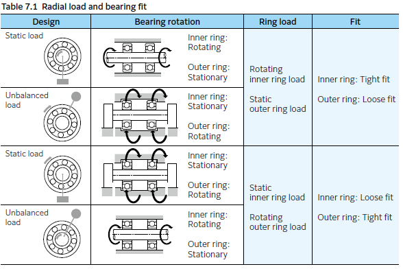
(1) For bearing rings under rotating loads, a tight fit is necessary. (Refer to Table 7.1) “Raceways under rotating loads” refers to raceways receiving loads rotating relative to their radial direction. For bearing rings under static loads, on the other hand, a loose fit is sufficient.
(Example) Rotating inner ring load = the direction of the radial load on the inner ring is rotating relatively
(2) For non-separable bearings, such as deep groove ball bearings, it is generally recommended that either the inner ring or outer ring be given a loose fit.

3.2. Recommended fits
Bearing fit is governed by the tolerances selected for bearing shaft diameters and housing bore diameters.
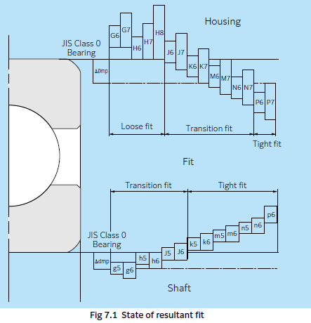
Widely used fits for Class 0 tolerance bearings and various shaft and housing bore diameter tolerances are shown in Fig. 7.1.
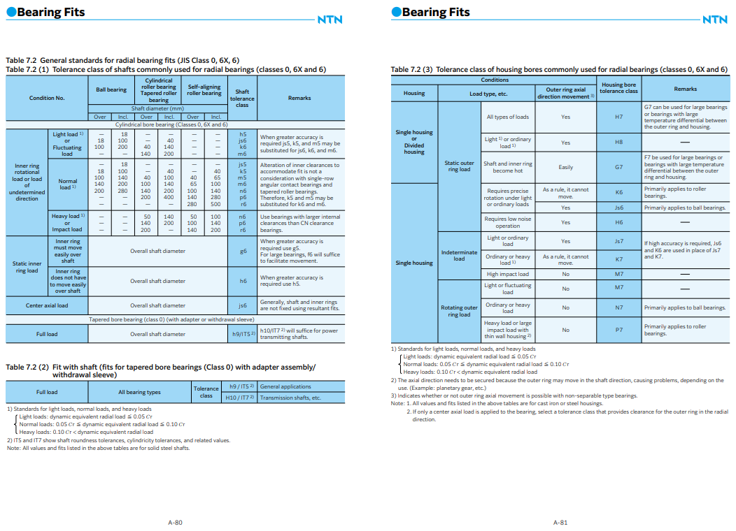
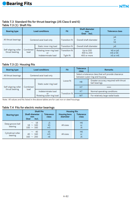
Generally-used, standard fits for most types of bearings and operating conditions are shown in Tables 7.2 to 7.7.
Table 7.2: Fits for radial bearings
Table 7.3: Fits for thrust bearings
Table 7.4: Fits for electric motor bearings
Table 7.6: Inch series tapered roller bearings Fits of (ANSI/ABMA CLASS 4)
Table 7.7: Inch series tapered roller bearings Fits of (ANSI/ABMA CLASS 3, CLASS 0)
Table 7.5 shows fits and their numerical values.
For special fits or applications, please consult NTN Engineering.
3.3. Interference minimum and maximum values
The following points should be considered when it is necessary to calculate the interference for an application:
- Regarding minimum values,
- interference is reduced by radial loads
- interference is reduced by differences between bearing temperature and ambient temperature
- interference is reduced by variation in mating surface
- interference is reduced by deformation
- The upper limit value should not exceed 1/ 1 000 of the shaft diameter. Required interference calculations are shown below.
(1) Mating surface variation and interference
Interference decreases because the mating surface is smoothed by the resultant fit (surface roughness is reduced). The amount the interference decreases depends on the roughness of the mating surfaces. It is generally necessary to anticipate the following decrease in interference.
For ground shafts: 1.0 to 2.5 μm
For machined shafts: 5.0 to 7.0 μm
The interference including this decrease amount is called effective interference.
(2) Radial loads and required interference
Interference of the inner ring and shaft decreases when a radial load is applied to the bearing. The interference required for installation to solid shafts is expressed by formulae (7.1) and (7.2) for each load condition.
General applications (Fr ≦ 0.3C0r)
Δ dF = 0.08(d ∙ Fr / B)1/2 N ············ (7.1)
Under heavy load conditions (Fr > 0.3 C0r)
Δ dF = 0.02(Fr / B) N ············ (7.2)
Where:
Δ dF : Required effective interference according to radial load μm
d : Bearing bore mm
B : Inner ring width mm
Fr : Actual radial load, N
C0r : Basic static load rating N
For solid shafts, please contact NTN Engineering.
(3) Temperature difference and required interference
Interference between inner rings and steel shafts is reduced as a result of temperature increases (difference between bearing temperature and ambient temperature, Δ T) caused by bearing rotation. Calculation of the minimum required amount of interference in such cases is shown in formula (7.3).
Δ dT = 0.0015 ∙ d ∙ Δ T ∙∙∙∙∙∙∙∙∙∙∙∙∙∙∙∙∙∙∙∙∙∙∙∙∙(7.3)
Δ dT : Required effective interference for temperature difference μm
Δ T : Difference between inner ring temperature and ambient temperature °C
d : Bearing bore mm
(4) Maximum interference
When bearing rings are installed with an interference fit, tensile or compressive stress may occur along their raceways. If interference is too great, this may cause damage to the rings and reduce bearing life. The maximum stress due to the resultant fit must not exceed approximately 127 MPa for safety. If the value is to be exceeded, consult NTN Engineering.
See section “17.4 Resultant fit surface pressure” for the calculation method of maximum stress due to the resultant fit.
(5) Interference change amount when materials other than steel are used for shafts and housings
When materials other than steel are used for shafts and housings, the fits between the inner ring and the shaft and the outer ring and the housing change because of difference in the expansion coefficient of each material as the temperature rises during the rotation of the bearing. Therefore, it is necessary to set the resultant fit with expansion coefficients in consideration. The calculation formula of the change in interference is shown below.
Δ dTE = (α1‒α2 )× d × Δ T
Δ dTE : Change in interference caused by difference in the expansion coefficients mm
α1 : Bearing expansion coefficient 1/°C
α2 : Shaft and housing expansion coefficient 1/°C
d : Reference dimension of resultant fit mm
Δ T : Temperature increase by bearing rotation °C
(Expansion coefficient: See Table 13.19 in “13. Bearing Materials.”)
3.4. Other details
(1) Large interference fits are recommended for,
- Operating conditions with large vibrations or shock loads
- Applications using hollow shafts or housings with thin walls
- Applications using housings made of light alloys or plastic
(2) Small interference fits are preferable for,
- Applications requiring high running accuracy
- Applications using small sized bearings or thin walled bearings
(3) Consideration must also be given to the fact that fit selection will effect internal bearing clearance selection. (refer to page A-88.)
(4) A particular type of fit is recommended for SL type cylindrical roller bearings. (refer to page C-67.)
(5) Bearing dimensions are measured and managed at a temperature of 20°C.


