Installation of tapered bore bearing
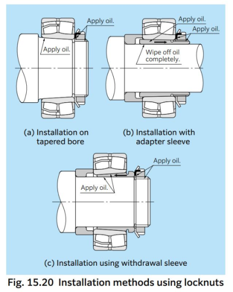
Small tapered bore bearings are installed by inserting a bearing a predetermined amount with locknuts and by using a tapered bore or an adapter sleeve/withdrawal sleeve. Locknuts are tightened by a hook spanner wrench (Fig. 15.20).

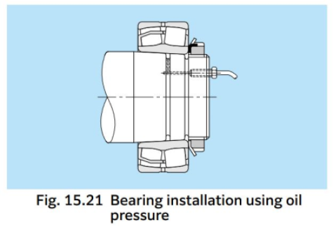
Large size bearings require considerable fitting force and must be installed hydraulically. In Fig. 15.21 the fitting surface friction and nut tightening torque needed to install bearings with tapered bores directly onto tapered shafts are decreased by injecting high pressure oil between the fitting surfaces.

Fig. 15.22 (a) shows a method of installation where a hydraulic nut is used to drive the bearing onto a tapered shaft. Fig. 15.19 (b) and (c) show installation methods using a hydraulic nut with adapter sleeves and withdrawal sleeves.
Fig. 15.23 shows an installation method using a hydraulic withdrawal sleeve.
With tapered bore bearings, as the inner ring is driven axially onto the shaft, adapter or withdrawal sleeve, the interference increases so that the bearing radial internal clearance will decrease. Interference can be estimated by measuring the decrease in radial internal clearance. As shown in Fig. 15.24, the radial internal clearance between the rollers and outer ring of spherical roller bearings should be measured with a thickness gauge under no load while the rollers are held in the correct position. Measure the radial internal clearance on both rows, and check that the values are equivalent. Instead of using the decrease in amount of radial internal clearance to estimate the interference, it is possible to estimate the mounted radial internal clearance by measuring the distance the bearing has been driven onto the shaft.
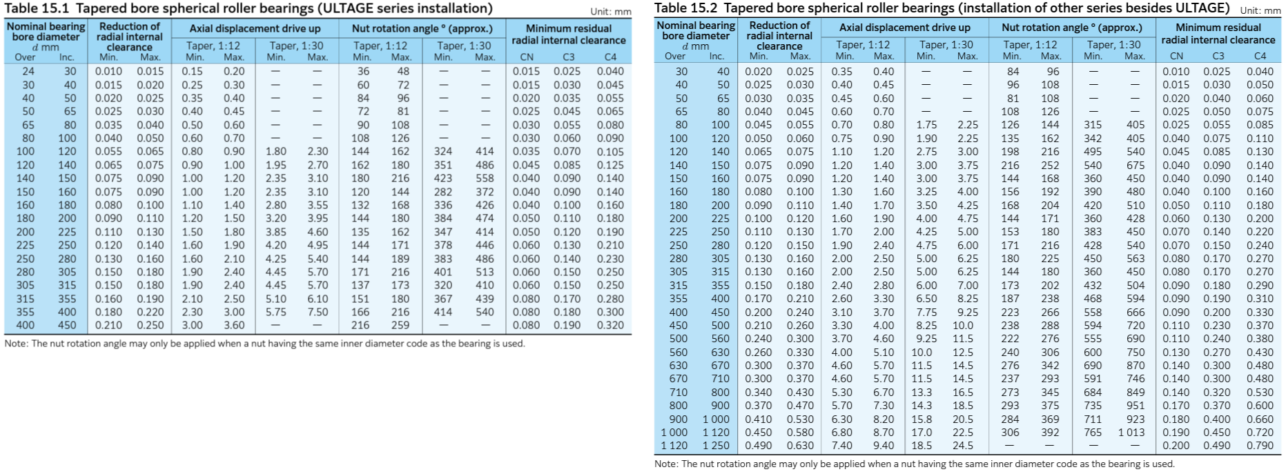
For conditions such as heavy loads, high speeds, or when there is a large temperature differential between inner and outer rings, etc. which require large interference fits, bearings with a minimum radial internal clearance of C3 or greater should be used. Table 15.1 and Table 15.2 list the maximum values for radial internal clearance decrease and axial displacement. The remaining clearance in mounted bearings with tapered bores must be greater than the minimum allowable residual clearance listed in Table 15.1 or Table 15.2.
For self-aligning ball bearings, a predetermined interference can be obtained by tightening the nut until the radial internal clearance becomes about half the size before the fitting. After installation, check that the bearing lightly and smoothly rotates.
